
My first homebrew computer!
2019-07-10
I've always wanted to design and build my own homebrew computer. By this, I mean buying some ICs and soldering together something like an Apple I or a ZX Spectrum.
This post isn't going to be about my struggles designing a homebrew PC, since I haven't done that. Instead, I bought a new Z80 homebrew kit, the RC 2014. That's right, there is still someone out there making these kits.
Why the Z80?
There are a few reasons I picked a Z80 as my first homebrew. The first is that you can buy a Z80 new from any reputable supplier: Zilog is still in business and still makes them new! You can just log onto DigiKey or whatever and add it to your basket.
The other is that you don't have to breadboard it: you can buy the RC2014 kit I linked to earlier, you just have to solder it together. I admit it's been a while since I've soldered anything but after getting this kit working, I can feel a desire to get the stripboard out and design some peripherals. So soldering is not a turn-off for me. This means you could theoretically build an entire Z80 computer without touching any wires (except the serial cable).
The other other reason is that there is an active community not just around the Z80 but around the RC2014 kit specifically. There are tons of modules people have designed and some you can even buy from them. And the creator of the RC2014 has a few available including an HDMI output, keyboard input, and more.
The build
I ordered online and I got my kit in the post. What did I get? A nice set of instructions, all of the resistors, capacitors, buttons and headers you need (no spares) and some PCBs. All as expected.
The instructions are very easy to follow and even include some troubleshooting tips.
The soldering iron I use is a cheap Chinese clone of a Hakko. It's temperature controlled and works with Hakko tips, so I would recommend it. It only cost 30 GBP and served me well for the (admittedly very small) amount of soldering I have done so far. No doubt if I get serious I'll end up having to buy something better. I would link it, but I am entirely unqualified to recommend soldering irons, so I won't. That's not the point of this post anyway.
I put the reset button I was given on the clock board and also added my own reset button (and 2k2 resistor) on the backplane. This is just because I found the clock board button hard to press without feeling like I was bending pins.
I chose not to use the barrel jack initially, instead opting to use power over the FTDI cable. This meant I had to put the jumper on the serial board to connect the 5V line from the FTDI cable.
And a side note: I didn't solder the right angle headers onto the ROM board very well, so it "leans back" and touches the serial board. I just used a folded up piece of card as a spacer to stop any shorts.
Problems
I connected my serial cable, and hit the reset button: nothing happened. Yes, my serial settings were correct and the cable was in the right way. Now what?
I don't have an oscilloscope capable of reading a 7 MHz signal, I just have a crappy handheld one that does maybe 200 kHz. This meant that I was restricted to the instructions for troubleshooting with a multimeter. Those instructions are very comprehensive by the way and did end up solving my problem.
I checked connectivity of all the lines: all good. No solder bridges either. But then I noticed that the voltage from the 5V line to ground was actually 3.3V. This should've been my first clue that my cheap Chinese FTDI cable was junk. Instead, I soldered on the barrel jack, moved the jumper so the board would take power from the jack instead of the FTDI cable, and moved on. All 5V lines were actually 5V now, at least.
The next step was building the signal tracer circuit on that troubleshooting page. As I understand it, this is just a spin on a differentiator circuit, since it gives a voltage only when the input voltage is changing. i.e. the output is related in some way to the derivative of the input voltage with respect to time.
Here is a photo of my breadboarded signal tracer:
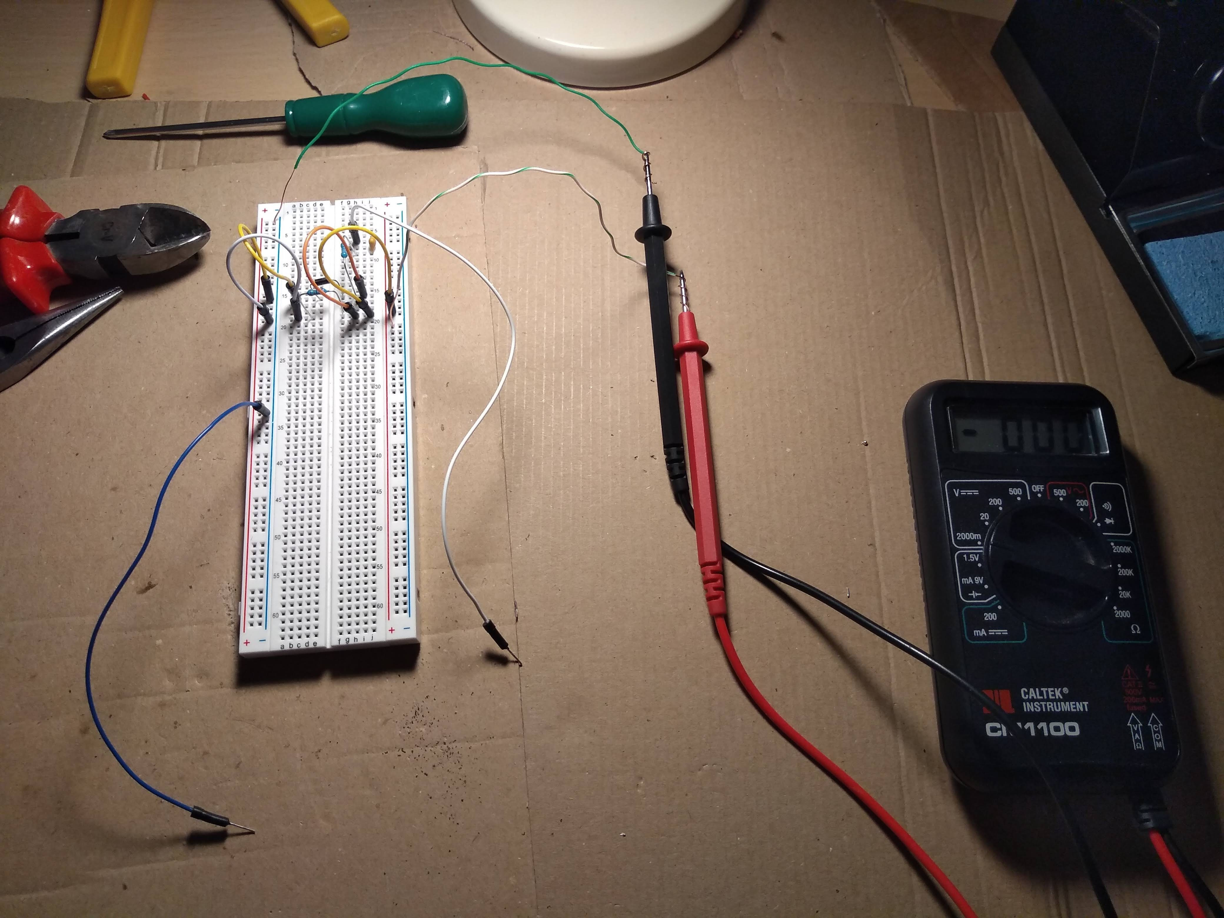
It worked like a charm and gave me some very useful info:
- There was a clock signal (good)
- Activity on the address lines, so the CPU was running a program
- Activity on the data lines, so the RAM and ROM probably worked (this wasn't conclusive, but they actually did work, so I never needed to check them in detail)
And here was the kicker that took me an age to notice: there was activity on the TX_Data pin of the serial communications controller (the MC68B50CP, on the serial board) but only if the FTDI cable was not connected. So the whole thing worked except the serial board!
I tried a different cable (a generic "Raspberry Pi debug cable", really a USB to TTL serial adapter) to no avail. Distraught, I emailed the RC2014-Z80 Google group and got some very good advice from the designer of the RC2014 himself, Spencer Owen. One of the things he wrote was that it was probably the serial cable not being sensitive enough - I should lower the values of the resistors on the TX and RX lines or just short them.
I shorted them and still my FTDI cable wasn't working! But then I tried my other generic Chinese cable and it worked!
The finished result
Here it is:
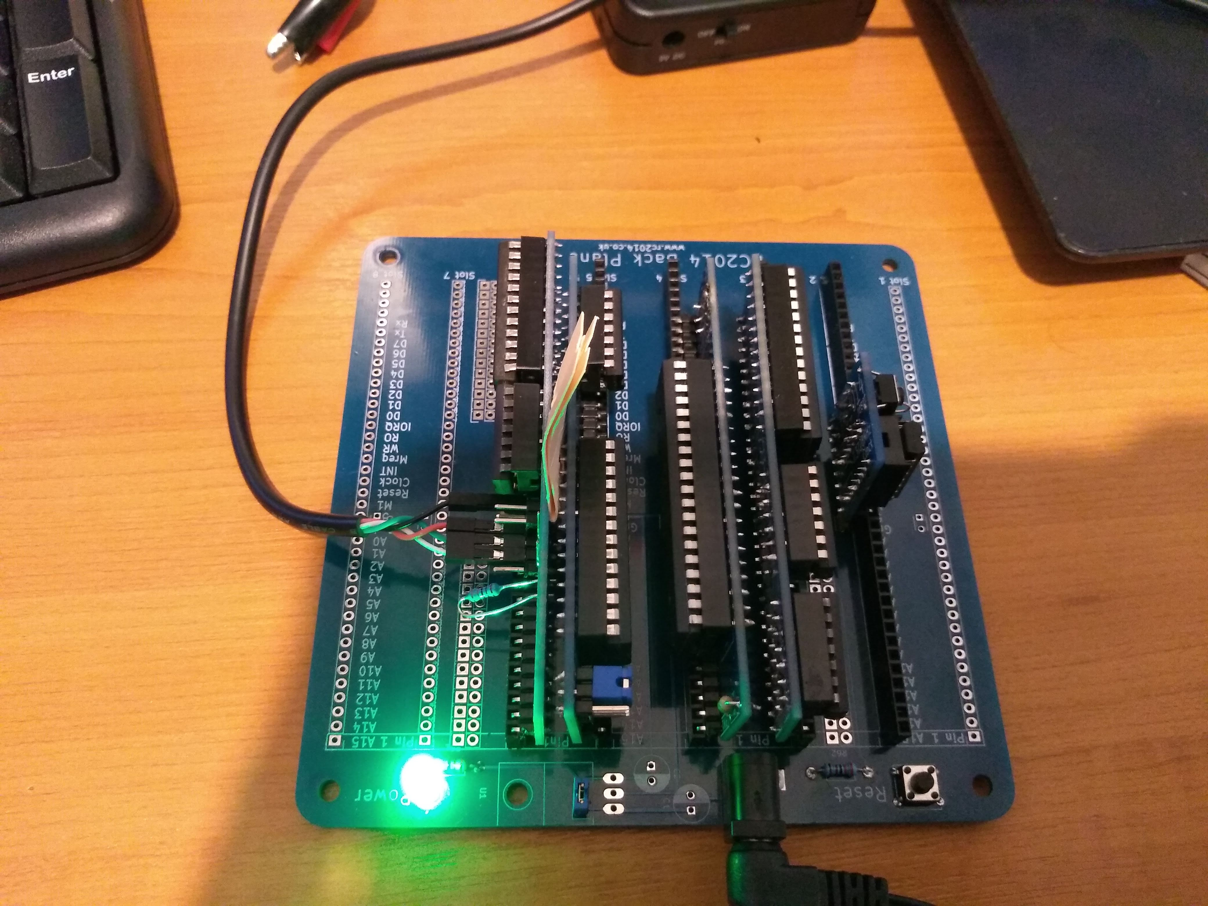
The resistor on the serial board is sticking out in an ugly way since this was while I was still in the middle of trying out different resistor values to see if I could get away with not shorting the connctions. Right now I just have them shorted and the serial controller gets a bit warm, which is probably not desirable.
Future steps
I look forward to writing some Z80 assembly programs, playing some BASIC games (including my favourite: Star Trek!) and designing some peripherals to use.
And if you're reading this, maybe you should check out the RC2014, it's a great kit for beginners (like me).